

Expansion tank and drain tank
Classification:
Expansion tank and drain tank
Details
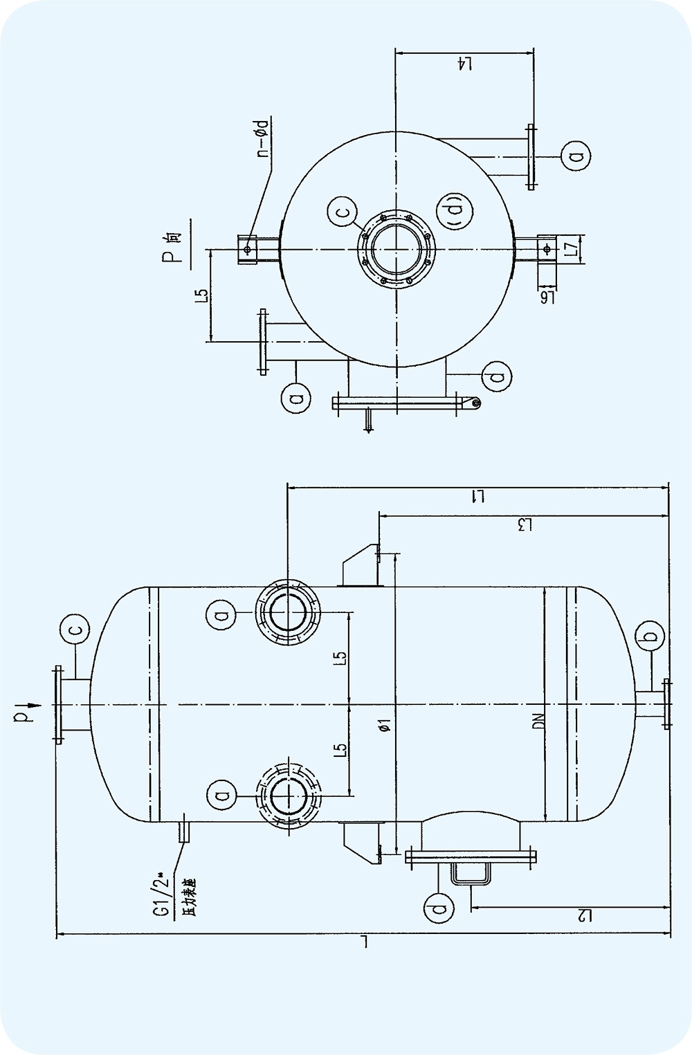
Condensate Expansion Tank
Use Purpose

This equipment is used to expand higher temperature and pressure condensate, separating steam and condensate. The steam can be introduced into a deaerator or other heat exchange equipment to utilize its heat energy, while the condensate can be introduced into condensate tanks and other equipment for recovery.
Technical Characteristics Table

|
|
SK-1 |
SK-1.5 |
SK-2 |
SK-2.5 |
|
Medium |
Steam, Water |
|||
|
Effective Volume (m3) |
1.0 |
1.5 |
2.0 |
2.5 |
|
Net Weight (kg) |
520 |
760 |
790 |
988 |
|
Full Water Weight (kg) |
1520 |
2360 |
2790 |
6488 |
Nominal Diameter of Pipe (DN)

|
Model |
Condensate Inlet (a) |
Condensate Outlet (b) |
Steam Outlet (c) |
Manhole (d) |
|
DN(mm) |
DN(mm) |
DN(mm) |
DN(mm) |
|
|
SK-1 |
100 |
100 |
200 |
400 |
|
SK-1.5 |
150 |
125 |
200 |
400 |
|
SK-2 |
150 |
150 |
250 |
400 |
|
SK-2.5 |
200 |
200 |
300 |
400 |
Dimensions Table (mm)

|
Model |
L |
L1 |
L2 |
L3 |
L4 |
L5 |
L6 |
L7 |
Φ1 |
DN |
d |
|
SK-1 |
2360 |
1300 |
|
1100 |
500 |
280 |
125 |
180 |
1020 |
800 |
24 |
|
SK-1.5 |
2500 |
1500 |
850 |
1300 |
650 |
380 |
160 |
205 |
1300 |
1000 |
30 |
|
SK-2 |
2650 |
1500 |
850 |
1300 |
750 |
480 |
200 |
290 |
1540 |
1200 |
30 |
|
SK-2.5 |
2730 |
1620 |
960 |
1400 |
800 |
500 |
250 |
330 |
1640 |
1300 |
30 |
External View

Periodic Blowdown Expansion Tank
Use Purpose

The periodic blowdown expansion tank expands and evaporates the boiler's periodic blowdown water, separating the steam and water.
Technical Characteristics Table

|
|
DP-0.8 |
DP-2 |
DP-3.5 |
DP-7.5 |
DP-8 |
DP-12 |
DP-15 |
DP-16 |
DP-30 |
|
Medium |
Steam, Water |
||||||||
|
Effective Volume (m3) |
0.8 |
2 |
3.5 |
7.5 |
8 |
12 |
15 |
16 |
30 |
|
Net Weight (kg) |
540 |
900 |
1300 |
2500 |
2600 |
2700 |
4500 |
5000 |
9000 |
|
Full Water Weight (kg) |
1340 |
2900 |
4800 |
10000 |
10600 |
14700 |
19500 |
21000 |
39000 |
Nominal Diameter of Pipe (DN)

|
Serial Number |
Wastewater Inlet (a) |
Steam Outlet (b) |
Wastewater Outlet (c) |
Manhole (d) |
|
DN(mm) |
DN(mm) |
DN(mm) |
DN(mm) |
|
|
DP-0.8 |
65 |
150 |
65 |
400 |
|
DP-2 |
65 |
150 |
65 |
400 |
|
DP-3.5 |
100 |
250 |
100 |
450 |
|
DP-7.5 |
150 |
300 |
150 |
450 |
|
DP-8 |
150 |
300 |
150 |
450 |
|
DP-12 |
200 |
450 |
200 |
450 |
|
DP-15 |
250 |
600 |
350 |
450 |
|
DP-16 |
250 |
600 |
350 |
450 |
|
DP-30 |
350 |
800 |
400 |
500 |
Dimensions Table (mm)

|
Model |
L |
L1 |
L2 |
L3 |
L4 |
L5 |
ΦD |
ΦD1 |
A |
n-Φd |
|
DP-0.8 |
2300 |
200 |
1050 |
1500 |
500 |
340 |
900 |
580 |
150 |
3-Φ20 |
|
DP-2 |
2550 |
215 |
870 |
1740 |
650 |
500 |
1200 |
790 |
160 |
4-Φ20 |
|
DP-3.5 |
3000 |
250 |
1200 |
2060 |
800 |
600 |
1400 |
900 |
210 |
4-Φ24 |
|
DP-7.5 |
3250 |
300 |
1320 |
2100 |
1000 |
800 |
2000 |
1310 |
250 |
4-Φ24 |
|
DP-8 |
3350 |
300 |
1420 |
2200 |
1000 |
800 |
2000 |
1310 |
250 |
4-Φ24 |
|
DP-12 |
4960 |
300 |
1350 |
2750 |
1000 |
800 |
2000 |
1310 |
250 |
4-Φ24 |
|
DP-15 |
4300 |
393 |
1400 |
2800 |
1250 |
1000 |
2500 |
1560 |
300 |
4-Φ24 |
|
DP-16 |
4650 |
630 |
1800 |
1890 |
1250 |
1000 |
2500 |
1560 |
300 |
4-Φ24 |
|
DP-30 |
5510 |
340 |
1360 |
3900 |
1600 |
1200 |
3000 |
1980 |
350 |
4-Φ24 |
Periodic Blowdown Expansion Tank Dimensions


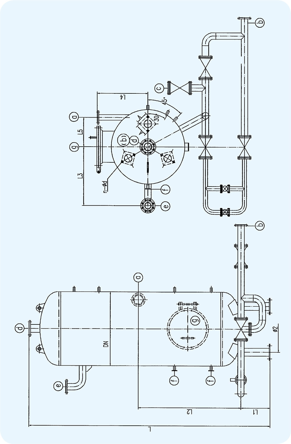
Continuous Blowdown Expansion Tank
Use Purpose

The continuous blowdown expansion tank expands and separates the boiler's continuous blowdown water, separating the steam and water. The heat from the steam and water is used as a heat source, improving the boiler's heat utilization efficiency.
Main Technical Parameters

|
|
LP-0.75 |
LP-1 |
LP-1.5 |
LP-2 |
LP-2.5 |
LP-3 |
LP-3.5 |
LP-5.5 |
|
Medium |
Steam, Water |
|||||||
|
Effective Volume (m3) |
0.75 |
1 |
1.5 |
2 |
2.5 |
3 |
3.5 |
5.5 |
|
Net Weight (kg) |
600 |
880 |
975 |
1100 |
1200 |
1950 |
2200 |
2500 |
|
Full Water Weight (kg) |
1350 |
1880 |
2475 |
3100 |
3700 |
4950 |
5700 |
8000 |
Dimensions Table

|
Model |
L |
L1 |
L2 |
L3 |
L4 |
L5 |
A |
N-Φ |
DN |
Φ2 |
|
LP-0.75 |
2800 |
\ |
1390 |
530 |
400 |
240 |
\ |
2-Φ20 |
650 |
\ |
|
LP-1 |
3520 |
200 |
1100 |
670 |
450 |
250 |
150 |
3-Φ20 |
750 |
480 |
|
LP-1.5 |
3500 |
420 |
1010 |
760 |
510 |
240 |
150 |
3-Φ20 |
800 |
500 |
|
LP-2 |
3400 |
420 |
1300 |
800 |
700 |
400 |
160 |
3-Φ20 |
1000 |
630 |
|
LP-2.5 |
3780 |
420 |
1430 |
800 |
700 |
400 |
160 |
3-Φ20 |
1000 |
630 |
|
LP-3 |
3900 |
420 |
1500 |
1000 |
900 |
450 |
160 |
3-Φ20 |
1200 |
790 |
|
LP-3.5 |
4050 |
420 |
1420 |
1000 |
900 |
450 |
160 |
3-Φ20 |
1200 |
790 |
|
LP-5.5 |
4200 |
420 |
1480 |
1050 |
800 |
600 |
210 |
3-Φ24 |
1500 |
980 |
Nominal Diameter of Pipe (DN)

|
Model |
Blowdown Water Inlet (a) |
Blowdown Water Outlet (b) |
Drainage Ditch (c) |
Steam Outlet (d) |
Safety Valve Interface (e) |
Electric Contact Level Gauge Interface (f) |
Manhole (g) |
|
LP-0.75 |
50 |
40 |
40 |
50 |
50 |
20 |
|
|
LP-1 |
50 |
50 |
50 |
80 |
65 |
20 |
|
|
LP-1.5 |
50 |
50 |
50 |
150 |
65 |
20 |
400 |
|
LP-2 |
65 |
65 |
65 |
100 |
80 |
20 |
400 |
|
LP-2.5 |
80 |
80 |
80 |
100 |
100 |
20 |
400 |
|
LP-3 |
100 |
100 |
100 |
150 |
100 |
20 |
450 |
|
LP-3.5 |
100 |
100 |
100 |
150 |
100 |
25 |
450 |
|
LP-5.5 |
150 |
125 |
125 |
150 |
150 |
25 |
450 |
Continuous Blowdown Expansion Tank Dimensions

WeChat Mini Program
WeChat public account
Service line:
Mobile:+86-15064136769
+86-13869137166
Mailbox:zhilin@sdzhilin.cn
Address: South Park, Jinan Economic Development Zone, Shandong Province