

Spiral plate heat exchanger
Shandong Zhilin Environmental Protection Technology Co., Ltd. is a professional heat exchanger manufacturer integrating the research, production, and sales of plate heat exchangers, spiral plate heat exchangers, detachable heat exchangers, high-efficiency plate heat exchangers, high-efficiency steam-water plate heat exchangers, high-efficiency intelligent heat exchanger units, plate heat exchanger units, and intelligent heat exchanger units. As a heat exchanger manufacturer, Zhilin Environmental Protection Technology's main products include plate heat exchangers, intelligent heat exchanger units, detachable heat exchangers, water-water plate heat exchangers, high-efficiency plate heat exchangers, gasket plate heat exchangers, detachable plate heat exchangers, and high-efficiency intelligent heat exchanger units. These are widely used in chemical, chemical fertilizer, pharmaceutical, petroleum, steel, liquor, food, beverage, printing and dyeing, power, coatings, rubber, heating, and hotel industries, and can also meet the requirements of heating, cooling, condensation, heat recovery, and various processes. Supported by strong technical strength, Zhilin Environmental Protection Technology, with its advanced production and testing equipment, perfect and scientific enterprise management, and harmonious and united production and sales team, does its utmost to provide customers with high-performance, reliable, and cost-effective products.
Classification:
Spiral plate heat exchanger
Details
Spiral Plate Heat Exchanger

A spiral plate heat exchanger is a new type of heat exchanger with high heat transfer efficiency, high operational stability, and the ability for multiple units to work together. It is a highly efficient heat exchange equipment suitable for steam-steam, steam-liquid, and liquid-liquid heat transfer.
It is applicable to the chemical, petroleum, solvent, pharmaceutical, food, light industry, textile, metallurgical, rolling, and coking industries. According to the structural form, it can be divided into non-dismountable (Type I) spiral plate and dismountable (Type II, Type III) spiral plate heat exchangers. The current standard is JB/T4751-2003 "Spiral Plate Heat Exchanger".
Structural Performance

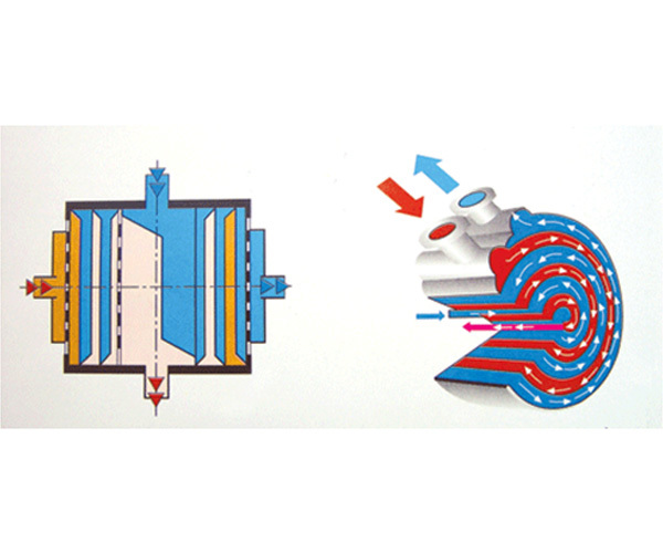
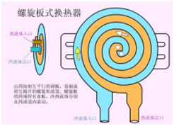 1. The spiral plate heat exchanger is made by parallel rolling of two plates, forming two uniform spiral channels. The two heat transfer media can perform full counter-current flow, greatly enhancing the heat exchange effect. Even with two media with small temperature differences, ideal heat exchange results can be achieved.
2. The nozzles on the shell adopt a tangential structure with low local resistance. Because the curvature of the spiral channel is uniform, the liquid flows in the equipment without sharp turns, resulting in low overall resistance. This allows for higher design flow rates and higher heat transfer capacity.
Basic Parameters

1. The nominal pressure PN of the spiral plate heat exchanger is specified as 0.6, 1, 1.6, and 2.5 MPa (i.e., the original 6, 10, 16, 25 kg/cm²) (referring to the maximum working pressure of a single channel). The test pressure is 1.25 times the working pressure.
2. Materials in contact with the medium in the spiral plate heat exchanger: carbon steel is Q235A, Q235B; stainless steel is SUS321, SUS304, 316L. Other materials can be selected according to user requirements.
3. Allowable operating temperature: carbon steel t=0-+350℃; stainless steel t=-40-500℃. The temperature rise and pressure drop range should comply with the relevant regulations for pressure vessels. When selecting this equipment, appropriate process calculations should be performed to ensure that the fluid in the equipment channel reaches a turbulent state (generally, liquid flow rate 1m/Sec, gas flow rate 10m/Sec). The equipment can be placed horizontally or vertically, but it can only be placed vertically when used for steam condensation; for caustic soda applications, overall heat treatment is required to eliminate stress.
4. When selecting the equipment, appropriate process calculations should be performed to ensure that the liquid in the equipment channel reaches a turbulent state (generally, liquid velocity ≥0.5m/s; gas ≥10m/s).
5. The equipment can be placed horizontally or vertically, but it can only be placed vertically when used for steam condensation.
6. For caustic soda applications, overall heat treatment is required to eliminate stress.
7. When the flow rate difference between the two sides of the channel is large, unequal spacing channels can be used to optimize the process design.
Features

1. High heat transfer efficiency: The spiral flow of fluid in the spiral plate heat exchanger generates centrifugal force, increasing the degree of turbulence. In addition, the distance columns in the channel also disrupt the boundary layer and create eddies. Therefore, turbulence can be formed at lower Reynolds numbers.
2. Countercurrent flow and low-temperature heat transfer: The two fluids can perform a complete countercurrent heat exchange in a long spiral channel.
3. Not easy to scale: The fluid in the spiral plate heat exchanger flows through a single channel, and its allowable flow rate is higher than that of other types of heat exchangers.
4. Compact structure, no pipe materials, and simple manufacturing.
Disadvantages:Spiral plate heat exchangers require high welding quality and are difficult to repair. They are heavy and have poor rigidity, requiring special attention during transportation and installation.
Leakage Handling

The spiral plate heat exchanger consists of two closed and independent spiral channels. If a leak occurs in the channel, it is difficult to determine the location of the leak. To accurately locate the leak point, a drilling method is used. When drilling, the drilling location should be on the same spiral channel at one end of the heat exchanger and arranged in a cross shape. When drilling, care should be taken to prevent iron filings from falling into the heat exchanger to keep the channels unobstructed.
Water Pressure Leak Test
Water is pumped into the heat exchanger from a non-drilled channel using a pressure water pump to create a certain pressure. At this time, the location of the leak in the heat exchanger will leak water into the other channel (the drilled channel) and drip down from the nearest drilled hole to the leak point (at this time, the drilled end of the heat exchanger should be placed downwards). By observing the location of the dripping water, it can be determined which layer has an internal leak. Then, a section of the end cover on the undrilled side of the same layer of the heat exchanger is cut open as an observation hole, and the specific leak point can be accurately determined from the observation hole.
WeChat Mini Program
WeChat public account
Service line:
Mobile:+86-15064136769
+86-13869137166
Mailbox:zhilin@sdzhilin.cn
Address: South Park, Jinan Economic Development Zone, Shandong Province